PowerVM QuickStart

Version 1.2.1
Date: 3/11/12

This document is minimally compatible with VIOS 1.5. VIOS 2.1 specific items are marked as such.

Overview

Virtualization Components

• (Whole) CPUs, (segments of) memory, and (physical) I/O devices can be assigned to an LPAR (Logical Partition). This is commonly referred to as dedicated resource partition (or Power 4 LPARs, as this capability was introduced with the Power 4 based systems).
• A DLPAR is the ability to dynamically add or remove resources from a running partition. All modern LPARs are DLPAR capable (even if the OS running on them is not). For this reason, DLPAR has more to do with the capabilities of the OS running in the LPAR than the LPAR itself. The acronym DLPAR is typically used as a verb (to add/remove a resource) as opposed to define a type of LPAR. Limits can be placed on DLPAR operations, but this is primarily a user imposed limit, not a limitation of the hypervisor.
• Slices of a CPU can be assigned to back a virtual processor in a partition. This is commonly referred to as a micro-partition (or commonly referred to as Power 5 LPAR, as this capability was introduced with the Power 5 based systems). Micro-partitions consume CPU from a shared pool of CPU resources.
• Power 5 and later systems introduced the concept of VIOS (Virtual I/O Server) that effectively allowed physical I/O resources to be shared amongst partitions.
• The IBM System P hypervisor is a Type 1 hypervisor with the option to provide shared I/O via a Type 2-ish software (VIOS) partition. The hypervisor does not own I/O resources (such as an Ethernet card), these can only be assigned to a LPAR. When owned by a VIOS LPAR they can be shared to other LPARs.
• Micro-Partitions in Power 6 systems can utilize multiple SPP (shared processor pools) to control CPU utilization to groups of micro-partitions.
• Some Power 6 systems introduced hardware based network virtualization with the IVE (Integrated Virtual Ethernet) device that allows multiple partitions to share a single Ethernet connection without the use of VIOS.
• Newer HBAs that offer NPIV (N Port ID Virtualization) can be used in conjunction with the appropriate VIOS version to present a virtualized HBA with a unique WWN directly to a client partition.
• VIOS 2.1 introduced memory sharing, only on Power 6 systems, that allows memory to be shared between two or more LPARs. Overcommitted memory can be paged to disk using a VIOS partition.
• VIOS and Micro-Partition technologies can be implemented independently. For example, a (CPU) Micro-Partition can be created with or without the use of VIOS.

PowerVM Acronyms & Definitions

CoD - Capacity on Demand. The ability to add compute capacity in the form of CPU or memory to a running system by simply activating it. The resources must be pre-staged in the system prior to use and are (typically) turned on with an activation key. There are several different pricing models for CoD.
DLPAR - Dynamic Logical Partition. This was used originally as a further clarification on the concept of an LPAR as one that can have resources dynamically added or removed. The most popular usage is as a verb; ie: to DLPAR (add) resources to a partition.
HEA - Host Ethernet Adapter. The physical port of the IVE interface on some of the Power 6 systems. A HEA port can be added to a port group and shared amongst LPARs or placed in promiscuous mode and used by a single LPAR (typically a VIOS LPAR).
HMC - Hardware Management Console. An "appliance" server that is used to manage Power 4, 5, and 6 hardware. The primary purpose is to enable / control the virtualization technologies as well as provide call-home functionality, remote console access, and gather operational data.
IVE - Integrated Virtual Ethernet. The capability to provide virtualized Ethernet services to LPARs without the need of VIOS. This functionality was introduced on several Power 6 systems.
IVM - Integrated Virtualization Manager. This is a management interface that installs on top of the VIOS software that provides much of the HMC functionality. It can be used instead of a HMC for some systems. It is the only option for virtualization management on the blades as they cannot have HMC connectivity.
LHEA - Logical Host Ethernet Adapter. The virtual interface of a IVE in a client LPAR. These communicate via a HEA to the outside / physical world.
LPAR - Logical Partition. This is a collection of system resources that can host an operating system. To the operating system this collection of resources appears to be a complete physical system. Some or all the resources on a LPAR may be shared with other LPARs in the physical system.
Lx86 - Additional software that allows x86 Linux binaries to run on Power Linux without recompilation.
MES - Miscellaneous Equipment Specification. This is a change order to a system, typically in the form of an upgrade. A RPO MES is for Record Purposes Only. Both specify to IBM changes that are made to a system.
MSPP - Multiple Shared Processor Pools. This is a Power 6 capability that allows for more than one SPP.
SEA - Shared Ethernet Adapter. This is a VIOS mapping of a physical to a virtual Ethernet adapter. A SEA is used to extend the physical network (from a physical Ethernet switch) into the virtual environment where multiple LPARs can access that network.
SPP - Shared Processor Pool. This is an organizational grouping of CPU resources that allows caps and guaranteed allocations to be set for an entire group of LPARs. Power 5 systems have a single SPP, Power 6 systems can have multiple.
VIOC - Virtual I/O Client. Any LPAR that utilizes VIOS for resources such as disk and network.
VIOS - Virtual I/O Server. The LPAR that owns physical resources and maps them to virtual adapters so VIOC can share those resources.

CPU Allocations

• Shared (virtual) processor partitions (Micro-Partitions) can utilize additional resources from the shared processor pool when available. Dedicated processor partitions can only use the "desired" amount of CPU, and only above that amount if another CPU is (dynamically) added to the LPAR.
• An uncapped partition can only consume up to the number of virtual processors that it has. (Ie: A LPAR with 5 virtual CPUs, that is backed by a minimum of .5 physical CPUs can only consume up to 5 whole / physical CPUs.) A capped partition can only consume up to its entitled CPU value. Allocations are in increments of 1/100th of a CPU, the minimal allocation is 1/10th of a CPU for each virtual CPU.
• All Micro-Partitions are guaranteed to have at least the entitled CPU value. Uncapped partitions can consume beyond that value, capped cannot. Both capped and uncapped relinquish unused CPU to a shared pool. Dedicated CPU partitions are guaranteed their capacity, cannot consume beyond their capacity, and on Power 6 systems, can relinquish CPU capacity to a shared pool.
• All uncapped micro-partitions using the shared processor pool compete for the remaining resources in the pool. When there is no contention for unused resources, a micro-partition can consume up to the number of virtual processors it has or the amount of CPU resources available to the pool.
• The physical CPU entitlement is set with the "processing units" values during the LPAR setup in the HMC. The values are defined as:
› Minimum: The minimum physical CPU resource required for this partition to start.
› Desired: The desired physical CPU resource for this CPU. In most situations this will be the CPU entitlement. The CPU entitlement can be higher if resources were DLPARed in or less if the LPAR started closer to the minimum value.
› Maximum: This is the maximum amount of physical CPU resources that can be DLPARed into the partition. This value does not have a direct bearing on capped or uncapped CPU utilization.
• The virtual CPU entitlement is set in the LPAR configuration much like the physical CPU allocation. Virtual CPUs are allocated in whole integer values. The difference with virtual CPUs (from physical entitlements) is that they are not a potentially constrained resource and the desired number is always received upon startup. The minimum and maximum numbers are effectively limits on DLPAR operations.
• Processor folding is an AIX CPU affinity method that insures that an AIX partition only uses as few CPUs as required. This is achieved by insuring that the LPAR uses a minimal set of physical CPUs and idles those it does not need. The benefit is that the system will see a reduced impact of configuring additional virtual CPUs. Processor folding was introduced in AIX 5.3 TL 3.
• When multiple uncapped micro-partitions compete for remaining CPU resources then the uncapped weight is used to calculate the CPU available to each partition. The uncapped weight is a value from 0 to 255. The uncapped weight of all partitions requesting additional resources is added together and then used to divide the available resources. The total amount of CPU received by a competing micro-partition is determined by the ratio of the partitions weight to the total of the requesting partitions. (The weight is not a nice value like in Unix.) The default priority for this value is 128. A partition with a priority of 0 is effectively a capped partition.
CPU Usage
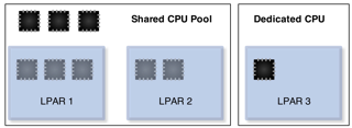
Figure 0: Virtualized and dedicated CPUs in a four CPU system with a single SPP.
• Dedicated CPU partitions do not have a setting for virtual processors. LPAR 3 in Figure 0 has a single dedicated CPU.
• LPAR 1 and LPAR2 in Figure 0 are Micro-Partitions with a total of five virtual CPUs backed by three physical CPUs. On a Power 6 system, LPAR 3 can be configured to relinquish unused CPU cycles to the shared pool where they will be available to LPAR 1 and 2 (provided they are uncapped).

Shared Processor Pools

• While SPP (Shared Processor Pool) is a Power 6 convention, Power 5 systems have a single SPP commonly referred to as a "Physical Shared Processor Pool". Any activated CPU that is not reserved for, or in use by a dedicated CPU LPAR, is assigned to this pool.
• All Micro-Partitions on Power 5 systems consume and relinquish resources from/to the single / physical SPP.
• The default configuration of a Power 6 system will behave like a Power 5 system in respect to SPPs. By default, all LPARs will be placed in the SPP0 / physical SPP.
• Power 6 systems can have up to 64 SPPs. (The limit is set to 64 because the largest Power 6 system has 64 processors, and a SPP must have at least 1 CPU assigned to it.)
• Power 6 SPPs have additional constraints to control CPU resource utilization in the system. These are:
• Desired Capacity - This is the total of all CPU entitlements for each member LPAR (at least .1 physical CPU for each LPAR). This value is changed by adding LPARs to a pool.
• Reserved Capacity - Additional (guaranteed) CPU resources that are assigned to the pool of partitions above the desired capacity. By default this is set to 0. This value is changed from the HMC as an attribute of the pool.
• Entitled Capacity - This is the total guaranteed processor capacity for the pool. It includes the guaranteed processor capacity of each partition (aka: Desired) as well as the Reserved pool capacity. This value is a derived value and is not directly changed, it is a sum of two other values.
• Maximum Pool Capacity - This is the maximum amount of CPU that all partitions assigned to this pool can consume. This is effectively a processor cap that is expanded to a group of partitions rather than a single partition. This value is changed from the HMC as an attribute of the pool.
• Uncapped Micro-Partitions can consume up to the total of the virtual CPUs defined, the maximum pool capacity, or the unused capacity in the system - whatever is smaller.

PowerVM Types

• PowerVM inherits nearly all the APV (Advanced Power Virtualization) concepts from Power 5 based systems. It uses the same VIOS software and options as the previous APV.
• PowerVM is Power 6 specific only in that it enables features available exclusively on Power 6 based systems (ie: Multiple shared processor pools and partition mobility are not available on Power 5 systems.)
• PowerVM (and its APV predecessor) are optional licenses / activation codes that are ordered for a server. Each is licensed by CPU.
• PowerVM, unlike its APV predecessor, comes in several different versions. Each is tiered for price and features. Each of these versions is documented in the table on the right.
• PowerVM activation codes can be checked from the HMC, IVM, or from IBM records at this URL: http://www-912.ibm.com/pod/pod. The activation codes on the IBM web site will show up as type "VET" codes.
Express • Only available on limited lower-end P6 systems
• Maximum of 3 LPARs (1 VIOS and 2 VIOC)
• CPU Micro-Partitions with single processor pool
• VIOS/IVM only, no HMC support
• Dedicated I/O resources (in later versions)
Standard • Up to the maximum partitions supported on each server
• Multiple shared processor pools
• IVM or HMC managed
Premium • All options in Standard & Live Partition Mobility

• The VET codes from the IBM activation code web site can be decoded using the following "key":
XXXXXXXXXXXXXXXXXXXXXXXX0000XXXXXXExpress
XXXXXXXXXXXXXXXXXXXXXXXX2C00XXXXXXStandard
XXXXXXXXXXXXXXXXXXXXXXXX2C20XXXXXXEnterprise

VIOS (Virtual I/O Server)

• VIOS is a special purpose partition that can serve I/O resources to other partitions. The type of LPAR is set at creation. The VIOS LPAR type allows for the creation of virtual server adapters, where a regular AIX/Linux LPAR does not.
• VIOS works by owning a physical resource and mapping that physical resource to virtual resources. Client LPARs can connect to the physical resource via these mappings.
• VIOS is not a hypervisor, nor is it required for sub-CPU virtualization. VIOS can be used to manage other partitions in some situations when a HMC is not used. This is called IVM (Integrated Virtualization Manager).
• Depending on configurations, VIOS may or may not be a single point of failure. When client partitions access I/O via a single path that is delivered via in a single VIOS, then that VIOS represents a potential single point of failure for that client partition.
• VIOS is typically configured in pairs along with various multipathing / failover methods in the client for virtual resources to prevent the VIOS from becoming a single point of failure.
• Active memory sharing and partition mobility require a VIOS partition. The VIOS partition acts as the controlling device for backing store for active memory sharing. All I/O to a partition capable of partition mobility must be handled by VIOS as well as the process of shipping memory between physical systems.

VIO Redundancy

• Fault tolerance in client LPARs in a VIOS configuration is provided by configuring pairs of VIOS to serve redundant networking and disk resources. Additional fault tolerance in the form of NIC link aggregation and / or disk multipathing can be provided at the physical layer to each VIOS server. Multiple paths / aggregations from a single VIOS to a VIOC do not provide additional fault tolerance. These multiple paths / aggregations / failover methods for the client are provided by multiple VIOS LPARs. In this configuration, an entire VIOS can be lost (ie: rebooted during an upgrade) without I/O interruption to the client LPARs.
• In most cases (when using AIX) no additional configuration is required in the VIOC for this capability. (See discussion below in regards to SEA failover vs. NIB for network, and MPIO vs. LVM for disk redundancy.)
• Both virtualized network and disk redundancy methods tend to be active / passive. For example, it is not possible to run EtherChannel within the system, from a VIOC to a single VIOS.
• It is important to understand that the performance considerations of an active / passive configuration are not relevant inside the system as all VIOS can utilize pooled processor resources and therefore gain no significant (internal) performance benefit by active / active configurations. Performance benefits of active / active configurations are realized when used to connect to outside / physical resources such as EtherChannel (port aggregation) from the VIOS to a physical switch.

VIOS Setup & Management

VIOS Management Examples

Accept all VIOS license agreements
license -accept
(Re)Start the (initial) configuration assistant
cfgassist
Shutdown the server
shutdown
›››    Optionally include -restart
List the version of the VIOS system software
ioslevel
List the boot devices for this lpar
bootlist -mode normal -ls
List LPAR name and ID
lslparinfo
Display firmware level of all devices on this VIOS LPAR
lsfware -all
Display the MOTD
motd
Change the MOTD to an appropriate message
motd "*****    Unauthorized access is prohibited!    *****"
List all (AIX) packages installed on the system
lssw
›››    Equivalent to lslpp -L in AIX
Display a timestamped list of all commands run on the system
lsgcl
To display the current date and time of the VIOS
chdate
Change the current time and date to 1:02 AM March 4, 2009
chdate -hour 1 \
       -minute 2 \
       -month 3 \
       -day 4 \
       -year 2009
Change just the timezone to AST
chdate -timezone AST (Visible on next login)
›››   The date command is availible and works the same as in Unix.
Brief dump of the system error log
errlog
Detailed dump of the system error log
errlog -ls | more
Remove error log events older than 30 days
errlog -rm 30
›››   The errlog command allows you to view errors by sequence, but does not give the sequence in the default format.
 
• errbr works on VIOS provided that the errpt command is in padmin's PATH.

VIOS Networking Examples

Enable jumbo frames on the ent0 device
chdev -dev ent0 -attr jumbo_frames=yes
View settings on ent0 device
lsdev -dev ent0 -attr
List TCP and UDP sockets listening and in use
lstcpip -sockets -family inet
List all (virtual and physical) ethernet adapters in the VIOS
lstcpip -adapters
Equivalent of no -L command
optimizenet -list
Set up initial TCP/IP config (en10 is the interface for the SEA ent10)
mktcpip -hostname vios1 \
        -inetaddr 10.143.181.207 \
        -interface en10 \
        -start -netmask 255.255.252.0 \
        -gateway 10.143.180.1
Find the default gateway and routing info on the VIOS
netstat -routinfo
List open (TCP) ports on the VIOS IP stack
lstcpip -sockets | grep LISTEN
Show interface traffic statistics on 2 second intervals
netstat -state 2
Show verbose statistics for all interfaces
netstat -cdlistats
Show the default gateway and route table
netstat -routtable
Change the default route on en0 (fix a typo from mktcpip)
chtcpip -interface en0 \
        -gateway \
        -add 192.168.1.1 \
        -remove 168.192.1.1
Change the IP address on en0 to 192.168.1.2
chtcpip -interface en0 \
        -inetaddr 192.168.1.2 \
        -netmask 255.255.255.0

VIOS Unix Subsystem

• The current VIOS runs on an AIX subsystem. (VIOS functionality is available for Linux. This document only deals with the AIX based versions.)
• The padmin account logs in with a restricted shell. A root shell can be obtained by the oem_setup_env command.
• The root shell is designed for installation of OEM applications and drivers only. It may be required for a small subset of commands. (The purpose of this document is to provide a listing of most frequent tasks and the proper VIOS commands so that access to a root shell is not required.)
• The restricted shell has access to common Unix utilities such as awk, grep, sed, and vi. The syntax and usage of these commands has not been changed in VIOS. (Use "ls /usr/ios/utils" to get a listing of available Unix commands.)
• Redirection to a file is not allowed using the standard ">" character, but can be accomplished with the "tee" command.
 
Redirect the output of ls to a file
ls | tee ls.out
Determine the underlying (AIX) OS version (for driver install)
oem_platform_level
Exit the restricted shell to a root shell
oem_setup_env
Mirror the rootvg in VIOS to hdisk1
extendvg rootvg hdisk1
mirrorios hdisk1
›››    The VIOS will reboot when finished

User Management

• padmin is the only user for most configurations. It is possible to configure additional users, such as operational users for monitoring purposes.
 
List attributes of the padmin user
lsuser padmin
List all users on the system
lsuser
›››   The optional parameter "ALL" is implied with no parameter.
Change the password for the current user
passwd

Virtual Disk Setup & Management

Virtual Disk Setup

• Disks are presented to VIOC by creating a mapping between a physical disk or storage pool volume and the vhost adapter that is associated with the VIOC.
• Best practices configuration suggests that the connecting VIOS vhost adapter and the VIOC vscsi adapter should use the same slot number. This makes the typically complex array of virtual SCSI connections in the system much easier to comprehend.
• The mkvdev command is used to create a mapping between a physical disk and the vhost adapter.
Create a mapping of hdisk3 to the virtual host adapter vhost2.
mkvdev -vdev hdisk3 \
       -vadapter vhost2 \
       -dev wd_c3_hd3
›››   It is called wd_c3_hd3 for "WholeDisk_Client3_HDisk3". The intent of this naming convention is to relay the type of disk, where from, and who to.
Delete the virtual target device wd_c3_hd3
rmvdev -vtd wd_c3_hd3
Delete the above mapping by specifying the backing device hdisk3
rmvdev -vdev hdisk3

Disk Redundancy in VIOS

• LVM mirroring can be used to provide disk redundancy in a VIOS configuration. One disk should be provided through each VIOS in a redundant VIOS config to eliminate a VIOS as a single point of failure.
• LVM mirroring is a client configuration that mirrors data to two different disks presented by two different VIOS.
• Disk path redundancy (assuming an external storage device is providing disk redundancy) can be provided by a dual VIOS configuration with MPIO at the client layer.
• Newer NPIV (N Port ID Virtualization) capable cards can be used to provide direct connectivity of the client to a virtualized FC adapter. Storage specific multipathing drivers such as PowerPath or HDLM can be used in the client LPAR. NPIV adapters are virtualized using VIOS, and should be used in a dual-VIOS configuration.
• MPIO is automatically enabled in AIX if the same disk is presented to a VIOC by two different VIOS.
• LVM mirroring (for client LUNs) is not recommended within VIOS (ie: mirroring your storage pool in the VIOS). This configuration would provide no additional protections over LVM mirroring in the VIOC.
• Storage specific multipathing drivers can be used in the VIOS connections to the storage. In this case these drivers should not then be used on the client. In figure 1, a storage vendor supplied multipathing driver (such as PowerPath) would be used on VIOS 1 and VIOS 2, and native AIX MPIO would be used in the client. This configuration gives access to all four paths to the disk and eliminates both VIOS and any path as a singe point of failure.
VIO Disk Paths
Figure 1: A standard disk multipathing scenario.

Virtual Optical Media

• Optical media can be assigned to an LPAR directly (by assigning the controller to the LPAR profile), through VIOS (by presenting the physical CD/DVD on a virtual SCSI controller), or through file backed virtual optical devices.
• The problem with assigning an optical device to an LPAR is that it may be difficult to manage in a multiple-LPAR system and requires explicit DLPAR operations to move it around.
• Assigning an optical device to a VIOS partition and re-sharing it is much easier as DLPAR operations are not required to move the device from one partition to another. cfgmgr is simply used to recognize the device and rmdev is used to "remove" it from the LPAR. When used in this manner, a physical optical device can only be accessed by one LPAR at a time.
• Virtual media is a file backed CD/DVD image that can be "loaded" into a virtual optical device without disruption to the LPAR configuration. CD/DVD images must be created in a repository before they can be loaded as virtual media.
• A virtual optical device will show up as a "File-backed Optical" device in lsdev output.
 
Create a 15 Gig virtual media repository on the clienthd storage pool
mkrep -sp clienthd -size 15G
Extend the virtual repository by an additional 5 Gig to a total of 20 Gig
chrep -size 5G
Find the size of the repository
lsrep
Create an ISO image in repository using .iso file
mkvopt -name fedora10 \
       -file /mnt/Fedora-10-ppc-DVD.iso -ro
Create a virtual media file directly from a DVD in the physical optical drive
mkvopt -name AIX61TL3 -dev cd0 -ro
Create a virtual DVD on vhost4 adapter
mkvdev -fbo -vadapter vhost4 \
       -dev shiva_dvd
›››   The LPAR connected to vhost4 is called shiva. shiva_dvd is simply a convenient naming convention.
Load the virtual optical media into the virtual DVD for LPAR shiva
loadopt -vtd shiva_dvd -disk fedora10iso
Unload the previously loaded virtual DVD (-release is a "force" option if the client OS has a SCSI reserve on the device.)
unloadopt -vtd shiva_dvd -release
List virtual media in repository with usage information
lsrep
Show the file backing the virtual media currently in murugan_dvd
lsdev -dev murugan_dvd -attr aix_tdev
Remove (delete) a virtual DVD image called AIX61TL3
rmvopt -name AIX61TL3

Storage Pools

• Storage pools work much like AIX VGs (Volume Groups) in that they reside on one or more PVs (Physical Volumes). One key difference is the concept of a default storage pool. The default storage pool is the target of storage pool commands where the storage pool is not explicitly specified.
• The default storage pool is rootvg. If storage pools are used in a configuration then the default storage pool should be changed to something other than rootvg.
 
List the default storage pool
lssp -default
List all storage pools
lssp
List all disks in the rootvg storage pool
lssp -detail -sp rootvg
Create a storage pool called client_boot on hdisk22
mksp client_boot hdisk22
Make the client_boot storage pool the default storage pool
chsp -default client_boot
Add hdisk23 to the client_boot storage pool
chsp -add -sp client_boot hdisk23
List all the physical disks in the client_boot storage pool
lssp -detail -sp client_boot
List all the physical disks in the default storage pool
lssp -detail
List all the backing devices (LVs) in the default storage pool
lssp -bd
›››   Note: This command does NOT show virtual media repositories. Use the lssp command (with no options) to list free space in all storage pools.
Create a client disk on adapter vhost1 from client_boot storage pool
mkbdsp -sp client_boot 20G \
       -bd lv_c1_boot \
       -vadapter vhost1
Remove the mapping for the device just created, but save the backing device
rmbdsp -vtd vtscsi0 -savebd
Assign the lv_c1_boot backing device to another vhost adapter
mkbdsp -bd lv_c1_boot -vadapter vhost2
Completely remove the virtual target device ld_c1_boot
rmbdsp -vtd ld_c1_boot
Remove last disk from the sp to delete the sp
chsp -rm -sp client_boot hdisk22
Create a client disk on adapter vhost2 from rootvg storage pool
mkbdsp -sp rootvg 1g \
       -bd murugan_hd1 \
       -vadapter vhost2 \
       -tn lv_murugan_1
›››   The LV name and the backing device (mapping) name is specified in this command. This is different than the previous mkbdsp example. The -tn option does not seem to be compatible with all versions of the command and might be ignored in earlier versions of the command. (This command was run on VIOS 2.1) Also note the use of a consistent naming convention for LV and mapping - this makes understanding LV usage a bit easier. Finally note that rootvg was used in this example because of limitations of available disk in the rather small example system it was run on - Putting client disk on rootvg does not represent an ideal configuration.

Virtual Network Setup & Management

SEA Setup - Overview

• The command used to set up a SEA (Shared Ethernet Adapter) is mkvdev.
• IP addresses cannot be configured on either the virtual or the physical adapter used in the mkvdev command. IP addresses are configured either on the SEA itself (created by the mkvdev -sea command) or another physical or virtual adapter that is not part of a SEA "bridge". (An example of the latter is seen in Figure 2.)
• Best practices suggest that IP addresses for the VIOS should not be created on the SEA but should be put on another virtual adapter in the VIOS attached to the same VLAN. This makes the IP configuration independent of any changes to the SEA. Figure 2, has an example of an IP address configured on a virtual adapter interface en1 and not any part of the SEA "path". (This is not the case when using SEA failover).
• The virtual device used in the SEA configuration should have "Access External Networks" (AKA: "Trunk adapter") checked in its configuration (in the profile on the HMC). This is the only interface on the VLAN that should have this checked. Virtual interfaces with this property set will receive all packets that have addresses outside the virtual environment. In figure 2, the interface with "Access External Networks" checked should be ent2.
• If multiple virtual interfaces are used on a single VLAN as trunk adapters then each must have a different trunk priority. This is typically done with multiple VIOS servers - with one virtual adapter from the same VLAN on each VIO server. This is required when setting up SEA Failover in the next section.
VIOS IP Config
Figure 2: Configuration of IP address on virtual adapter.
• The examples here are of SEAs handling only one VLAN. A SEA may handle more than one VLAN. The -default and -defaultid options to mkvdev -sea make more sense in this (multiple VLAN) context.

Network Redundancy in VIOS

• The two primary methods of providing network redundancy for a VIOC in a dual VIOS configuration are NIB (Network Interface Backup) and SEA Failover. (These provide protection from the loss of a VIOS or VIOS connectivity to a physical LAN.)
• NIB creates a link aggregation in the client of a single virtual NIC with a backup NIC. (Each virtual NIC is on a separate VLAN and connected to a different VIOS.) This configuration is done in each client OS. (See Figure 3 for an example of the VIOC that uses NIB to provide redundant connections to the LAN.)
• SEA Failover is a VIOS configuration option that provides two physical network connections, one from each VIOS. No client configuration is required as only one virtual interface is presented to the client.
• Most Power 6 based systems offer IVE (Integrated Virtual Ethernet) hardware that provides virtual NICs to clients. These do not provide redundancy and must be used in pairs or with another NIC / backup path on each client (or VIOS) to provide that capability. (Note: This is in the context of client NIB configurations. When IVE is used directly to the client different configuration rules apply. See the IVE Redpaper for the particulars of configuring IVE for aggregation and interface failover.)
• NIB and SEA Failover are not mutually exclusive and can be used together or with link aggregation (EtherChannel / 802.3ad) to a physical device in the VIOS. Figure 3 shows a link aggregation device (ent3) in VIOS 1 as the physical trunk adapter for the SEA (ent4) in what is seen by the client as a NIB configuration.
• Link aggregation (EtherChannel / 802.3ad) of more than one virtual adapter is not supported or necessary from the client as all I/O moves at memory speed in the virtual environment. The more appropriate method is to direct different kinds of I/O or networks to particular VIOS servers where they do not compete for CPU time.
VIOC NIC Failover
Figure 3: NIC failover implemented at the VIO Client layer along with additional aggregation/failover at the VIOS layer.
• The primary benefit of NIB (on the client) is that the administrator can choose the path of network traffic. In the case of figure 3, the administrator would configure the client to use ent0 as the primary interface and ent1 as the backup. Then more resources (in the form of aggregate links) can be used on VIOS1 to handle the traffic with traffic only flowing through VIOS2 in the event of a failure of VIOS1. The problem with this configuration is that it requires additional configuration on the client and is not conducive as SEA Failover to simplistic NIM installs.
• NIB configurations also allow the administrator to balance clients so that all traffic does not go to a single VIOS. In this case hardware resources would be configured more evenly than they are in figure 3 with both VIOS servers having similar physical connections as appropriate for a more "active / active" configuration.

SEA Setup - Example

Create a SEA "bridge" between the physical ent0 and the virtual ent2 (from Figure 2)
mkvdev -sea ent0 -vadapter ent2 \
       -default ent2 -defaultid 1
›››   Explanation of the parameters:
-sea ent0 -- This is the physical interface
-vadapter ent2 -- This is the virtual interface
-default ent2 -- Default virtual interface to send untagged packets
-defaultid 1 -- This is the PVID for the SEA interface
• The PVID for the SEA is relevant when the physical adapter is connected to a VLAN configured switch and the virtual adapter is configured for VLAN (802.3Q) operation. All traffic passed through the SEA should be untagged in a non-VLAN configuration.
• This example assumes that separate (physical and virtual) adapters are used for each network. (VLAN configurations are not covered in this document).

SEA Management

Find virtual adapters associated with SEA ent4
lsdev -dev ent4 -attr virt_adapters
Find control channel (for SEA Failover) for SEA ent4
lsdev -dev ent4 -attr ctl_chan
Find physical adapter for SEA ent4
lsdev -dev ent4 -attr real_adapter
List all virtual NICs in the VIOS along with SEA and backing devices
lsmap -all -net
List details of Server Virtual Ethernet Adapter (SVEA) ent2
lsmap -vadapter ent2 -net

SEA Failover

• Unlike a regular SEA adapter, a SEA failover configuration has a few settings that are different from stated best practices.
• A SEA failover configuration is a situation when IP addresses should be configured on the SEA adapter.
• A control channel must be configured between the two VIOS using two virtual ethernet adapters that use that VLAN strictly for this purpose. The local virtual adapter created for this purpose should be specified in the ctl_chan attribute in each of the SEA setups.
• Both virtual adapters (on the VLAN with clients) should be configured to "Access External network", but one should have a higher priority (lower number) for the "Trunk priority" option. A SEA failover configuration is the only time that you should have two virtual adapters on the same VLAN that are configured in this manner.
SEA Failover Setup
Figure 3: SEA Failover implemented in the VIOS layer.
The following command needs to be run on each of the VIOS to create a simple SEA failover. (It is assumed that interfaces match on each VIOS.)
mkvdev -sea ent0 -vadapter ent1 -default ent1
        -defaultid 1 -attr ha_mode=auto
        ctl_chan=ent3 netaddr=10.143.180.1
›››   Explanation of the parameters:
   -sea ent0 -- This is the physical interface
   -vadapter ent1 -- This is the virtual interface
   -default ent1 -- Default virtual interface to send untagged packets
   -defaultid 1 -- This is the PVID for the SEA interface
   -attr ha_mode=auto -- Turn on auto failover mode
   (-attr) ctl_chan=ent3 -- Define the control channel interface
   (-attr) netaddr=10.143.180.1 -- Address to ping for connect test
 
• auto is the default ha_mode, standby forces a failover situation
 
Change the device to standby mode (and back) to force failover
chdev -dev ent4 -attr ha_mode=standby
chdev -dev ent4 -attr ha_mode=auto
See what the priority is on the trunk adapter
netstat -cdlistats | grep "Priority"

VIOS Device Management

Disk

Determine if SCSI reserve is enabled for hdisk4
lsdev -dev hdisk4 -attr reserve_policy
Turn off SCSI reserve for hdisk4
chdev -dev hdisk4 -attr reserve_policy=no_reserve
Re-enable SCSI reserve for hdisk4
chdev -dev hdisk4 -attr reserve_policy=single_path
Enable extended disk statistics
chdev -dev sys0 -attr iostat=true
List the parent device of hdisk0
lsdev -dev hdisk0 -parent
List all the child devices of (DS4000 array) dar0
lsdev -dev dar0 -child
List the reserve policy for all disks on a DS4000 array
for D in `lsdev -dev dar0 -child -field name | grep -v name`
do
  lsdev -dev $D -attr reserve_policy
done

Devices

Discover new devices
cfgdev
›››   This is the VIOS equivalent of the AIX cfgmgr command.
List all adapters (physical and virtual) on the system
lsdev -type adapter
List only virtual adapters
lsdev -virtual -type adapter
List all virtual disks (created with mkvdev command)
lsdev -virtual -type disk
Find the WWN of the fcs0 HBA
lsdev -dev fcs0 -vpd | grep Network
List the firmware levels of all devices on the system
lsfware -all
›››   The invscout command is also available in VIOS.
Get a long listing of every device on the system
lsdev -vpd
List all devices (physical and virtual) by their slot address
lsdev -slots
List all the attributes of the sys0 device
lsdev -dev sys0 -attr
List the port speed of the (physical) ethernet adapter eth0
lsdev -dev ent0 -attr media_speed
List all the possible settings for media_speed on ent0
lsdev -dev ent0 -range media_speed
Set the media_speed option to auto negotiate on ent0
chdev -dev ent0 -attr media_speed=Auto_Negotiation
Set the media_speed to auto negotiate on ent0 on next boot
chdev -dev ent0 \
      -attr media_speed=Auto_Negotiation \
      -perm
Turn on disk performance counters
chdev -dev sys0 -attr iostat=true

Low Level Redundancy Configuration

• Management and setup of devices requiring drivers and tools not provided by VIOS (ie PowerPath devices) will require use of the root shell available from the oem_setup_env command.
• Tools installed from the root shell (using oem_setup_env) may not be installed in the PATH used by the restricted shell. The commands may need to be linked or copied to the correct path for the restricted padmin shell. Not all commands may work in this manner.
• The mkvdev -lnagg and cfglnagg commands can be used to set up and manage link aggregation (to external ethernet switches).
• The chpath, mkpath, and lspath commands can be used to manage MPIO capable devices.

Best Practices / Additional Notes

• Virtual Ethernet devices should only have 802.1Q enabled if you intend to run additional VLANs on that interface. (In most instances this is not the case).
• Only one interface should be configured to "Access External Networks" on a VLAN, this should be the virtual interface used for the SEA on the VIOS and not the VIOC. This is the "gateway" adapter that will receive packets with MAC addresses that are unknown. (This is also known as a "Trunk adapter" on some versions of the HMC.)
• VIOS partitions are unique in that they can have virtual host adapters. Virtual SCSI adapters in VIOC partitions connect to LUNs shared through VIOS virtual host adapters.
• An organized naming convention to virtual devices is an important method to simplifying complexity in a VIOS environment. Several methods are used in this document, but each represents a self-documenting method that relates what the virtual device is and what it serves.
• VIOS commands can be run from the HMC. This may be a convenient alternative to logging into the VIOS LPAR and running the command.
• Power 6 based systems have an additional LPAR parameter called the partition "weight". The additional RAS features will use this value in a resource constrained system to kill a lower priority LPAR in the event of a CPU failure.
• The ratio of virtual CPUs in a partition to the actual amount of desired / entitled capacity is a "statement" on the partitions ability to be virtualized. A minimal backing of actual (physical) CPU entitlement to a virtual CPU suggests that the LPAR will most likely not be using large amounts of CPU and will relinquish unused cycles back to the shared pool the majority of the time. This is a measure of how over-committed the partition is.
• multiple profiles created on the HMC can represent different configurations such as with and without the physical CD/DVD ROM. These profiles can be named (for example) as <partition_name>_prod and <partition_name>_cdrom.
• HMC partition configuration and profiles can be saved to a file and backed up to either other HMCs or remote file systems.
• sysplan files can be created on the HMC or the SPT (System Planning Tool) and exported to each other. These files are a good method of expressing explicit configuration intent and can serve as both documentation as well as a (partial) backup method of configuration data.
• vhost adapters should be explicitly assigned and restricted to client partitions. This helps with documentation (viewing the config in the HMC) as well as preventing trespass of disks by other client partitions (typically due to user error).

Key VIOS Commands

VIOS commands are documented by categories on this InfoCenter page.

The lsmap command

• Used to list mappings between virtual adapters and physical resources.
List all (virtual) disks attached to the vhost0 adapter
lsmap -vadapter vhost0
List only the virtual target devices attached to the vhost0 adapter
lsmap -vadapter vhost0 -field vtd
This line can be used as a list in a for loop
lsmap -vadapter vhost0 -field vtd -fmt :|sed -e "s/:/ /g"
List all shared ethernet adapters on the system
lsmap -all -net -field sea
List all (virtual) disks and their backing devices
lsmap -all -type disk -field vtd backing
List all SEAs and their backing devices
lsmap -all -net -field sea backing
 

The mkvdev command

• Used to create a mapping between a virtual adapter and a physical resource. The result of this command will be a "virtual device".
 
Create a SEA that links physical ent0 to virtual ent1
mkvdev -sea ent0 -vadapter ent1 -default ent1 -defaultid 1
›››   The -defaultid 1 in the previous command refers to the default VLAN ID for the SEA. In this case it is set to the VLAN ID of the virtual interface (the virtual interface in this example does not have 802.1q enabled).
›››   The -default ent1 in the previous command refers to the default virtual interface for untagged packets. In this case we have only one virtual interface associated with this SEA.
Create a disk mapping from hdisk7 to vhost2 and call it wd_c1_hd7
mkvdev -vdev hdisk7 -vadapter vhost2 -dev wd_c1_hd7
Remove a virtual target device (disk mapping) named vtscsi0
rmvdev -vtd vtscsi0
 

Advanced VIOS Management

Performance Monitoring

Retrieve statistics for ent0
entstat -all ent0
Reset the statistics for ent0
entstat -reset ent0
View disk statistics (every 2 seconds)
viostat 2
Show summary for the system in stats
viostat -sys 2
Show disk stats by adapter (useful to see per-partition (VIOC) disk stats)
viostat -adapter 2
Turn on disk performance counters
chdev -dev sys0 -attr iostat=true
• The topas command is available in VIOS but uses different command line (start) options. When running, topas uses the standard AIX single key commands and may refer to AIX command line options.
 
View CEC/cross-partition information
topas -cecdisp

Backup

Create a mksysb file of the system on a NFS mount
backupios -file /mnt/vios.mksysb -mksysb
Create a backup of all structures of (online) VGs and/or storage pools
savevgstruct vdiskvg (Data will be saved to /home/ios/vgbackups)
List all (known) backups made with savevgstruct
restorevgstruct -ls
Backup the system (mksysb) to a NFS mounted filesystem
backupios -file /mnt
• sysplan files can be created from the HMC per-system menu in the GUI or from the command line using mksysplan.
• Partition data stored on the HMC can be backed up using (GUI method): per-system pop-up menu -> Configuration -> Manage Partition Data -> Backup

VIOS Security

List all open ports on the firewall configuration
viosecure -firewall view
To view the current security level settings
viosecure -view -nonint
Change system security settings to default
viosecure -level default
To enable basic firewall settings
viosecure -firewall on
List all failed logins on the system
lsfailedlogin
Dump the Global Command Log (all commands run on system)
lsgcl

About this QuickStart

Created by: William Favorite (wfavorite@tablespace.net)
Updates at: http://www.tablespace.net
Disclaimer: This document is a guide and it includes no express warranties to the suitability, relevance, or compatibility of its contents with any specific system. Research any and all commands that you inflict upon your command line.
Distribution:Copies of this document are free to redistribute as long as credit to the author and tablespace.net is retained in the printed and electronic versions.